
Ethan Huang
2nd Year Electrical Engineering Student
at Carleton University

2nd Year Electrical Engineering Student
at Carleton University
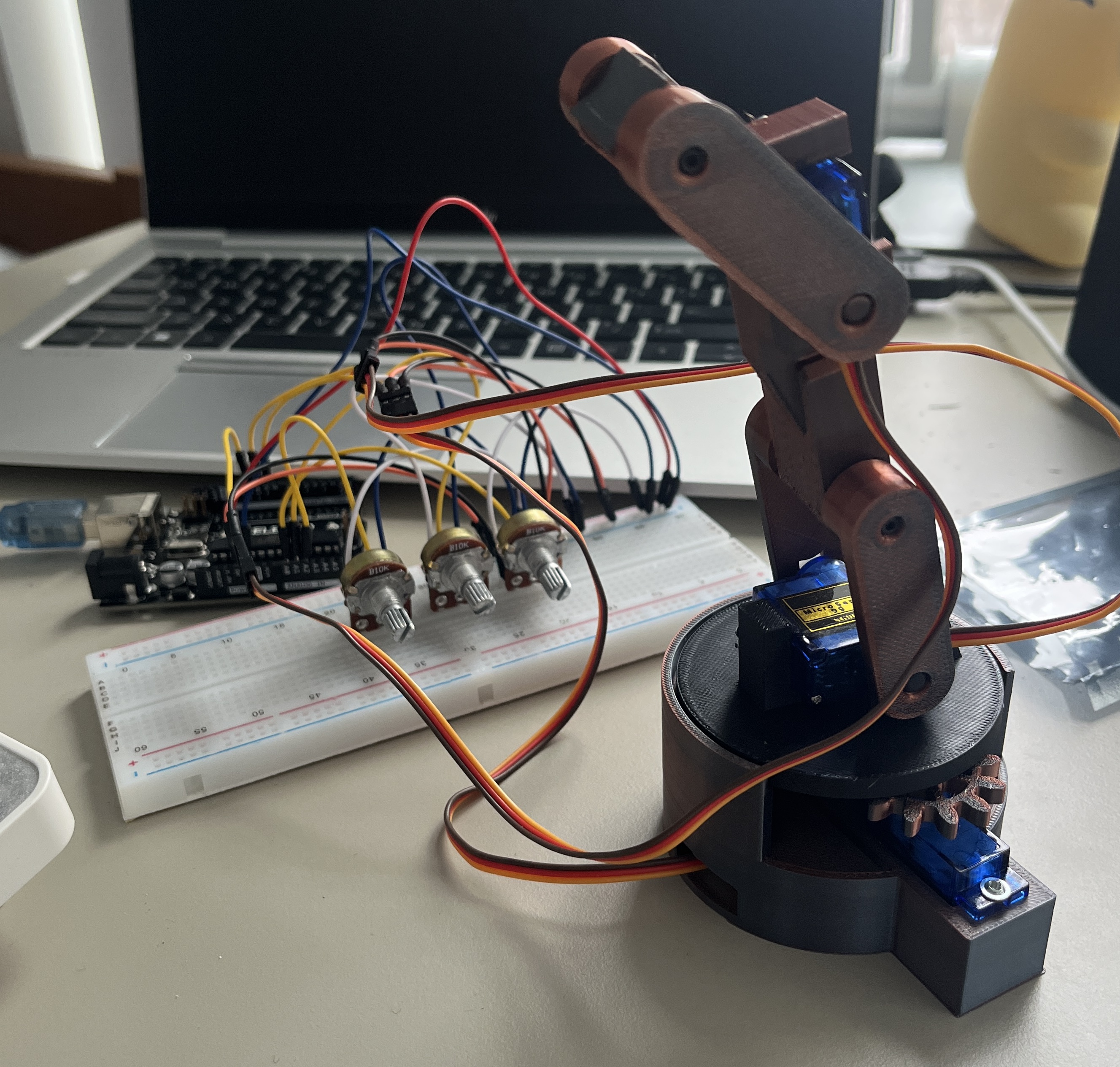

Developed an Arduino-controlled robotic arm, prototyping and testing the circuit on a breadboard
Programmed servo motor control in C++ using the Arduino IDE to enable precise arm movement
Used a potentiometer as an analog input for real-time control of the arm's position
Designed the robot arm chassis and gears using 3D CAD software
Video demonstration of Robotic Arm being controlled by potentiometers.
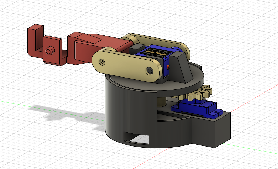
3D CAD Model of Robotic Arm made in Fusion 360
The RED component is a segment which houses a servo motor, and theoretically allows for infinite stages to allow for range of motion.
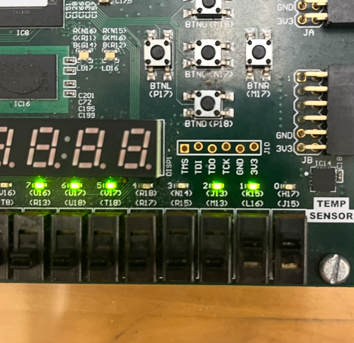
Designed a digital vehicle brake and turn-signal control system using Verilog HDL, defining the system’s logic and state behavior
Implemented both combinational and sequential logic, including D flip-flops and clock division, to manage signal timing and control flow
Verified correct operation through comprehensive testbench simulations in Xilinx Vivado
Synthesized the design and deployed it onto a Nexys A7 FPGA board for hardware-level validation
Video demonstration of the Brake Lights Verilog circuit after being synthesized onto the FPGA Board for visual representation.
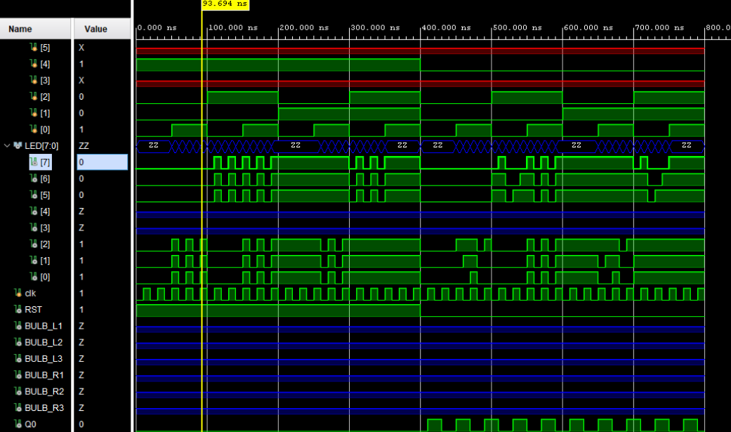
Brake Light Module Testbench Time Diagram
Testbench module output written in Verilog to simulate the behaviours of logic circuit before synthesizing onto FPGA Board.
Designed and built a custom brushless DC motor, integrating mechanical and electrical components into a functional system
Modeled the motor housing and structural components in Fusion 360 and fabricated them using a Bambu Lab P1 3D printer
Integrated permanent magnets, a LiPo battery, ESC, and servo tester to drive and control the motor
Soldered and assembled all electrical connections, applying electromagnetic and DC motor theory to achieve reliable operation
Video demonstration of DC Motor spinning, controlled by servo tester.
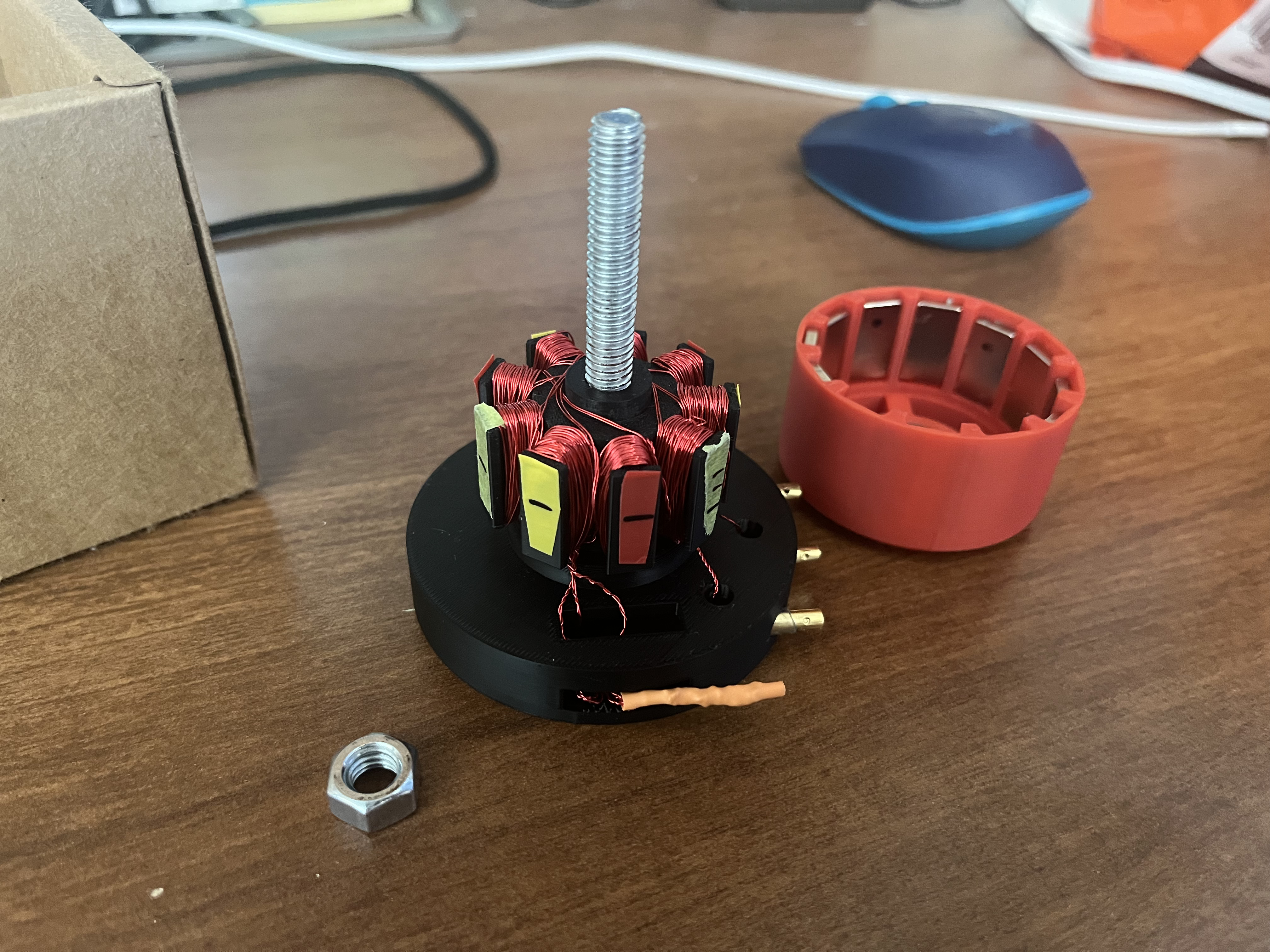
DC Motor Assembly presenting the motor's stator(on the left) and the rotor(on the right).
The stator is made from 3 seperate copper wires which are winded around the red, yellow, and green components respectively.
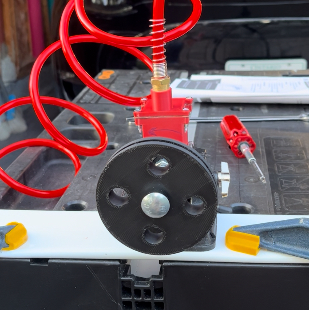
Designed and built a compressed air engine from scratch, demonstrating the mechanical operation of pistons and engine systems
Modeled all engine components in Fusion 360 and fabricated them using a Bambu Lab P1 3D printer
Applied 3D printing dimension and tolerance constraints to ensure proper fit, motion, and air sealing between components
Assembled and tested the engine using a compressed air supply, safely operating an air compressor to validate functionality
Video demonstration of the Compressed Air Engine rotor spinning.
!!! AUDIO WARNING !!!
Nuts and Bolts attached to rotor are to provide extra mass for increased momentum.

3D CAD Model of Air Engine made in Fusion 360
The RED component represents a ball bearing, and the YELLOW component represents a bolt used as an axle. The rest of the components were 3D printed.
Get in Touch